Skip to content

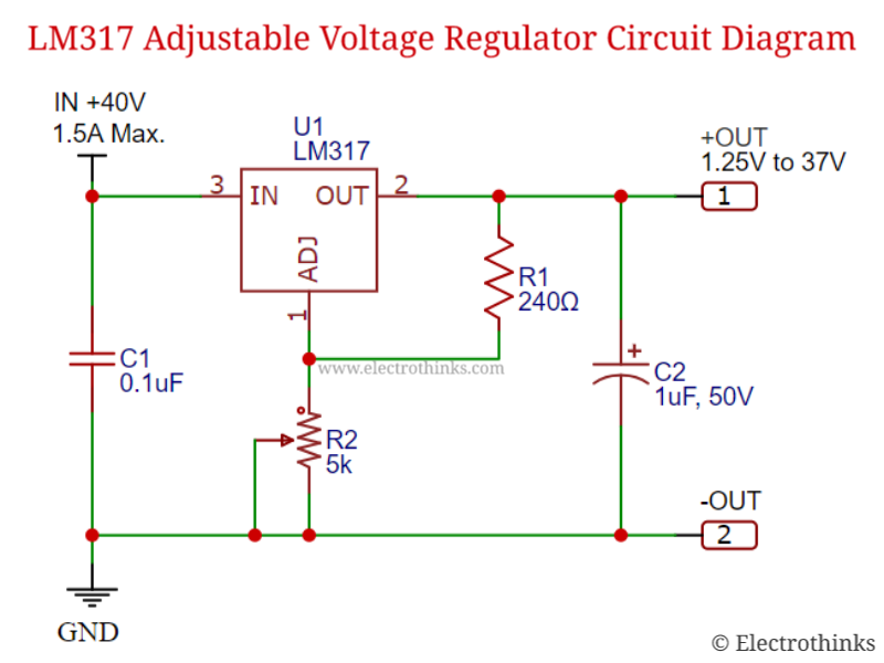
Adjustable Voltage Regulator Circuit Diagram Use Ne555 Ic Ne

Solved Design and implement a circuit with a NE555 | Chegg.com

How does ne555 timer circuit work Ne555 inverter circuit read wiring Adjustable timer circuit using 555

Solved Design and implement a circuit with a NE555 | Chegg.com

How to power raspberry pi pico with batteries: li-ion, 9v, 12v, aa, aaa Megsemmisítés afrikai udvariasság variable power supply using lm317 How does ne555 timer circuit work

Ne555 motor regulator

Propósito y explicación de la resistencia cerca de la salida de lm317Timer 555 ne555 datasheet pinout eleccircuit lm555 flop Adjustable voltage regulator circuitLm350 adjustable voltage regulator.

Using an adjustable voltage regulator for electronic diagnosisOn video lm317 adjustable voltage regulator 0-30v 30a Circuit intégré de minuterie 555Solved design and implement a circuit with a ne555.

Ne555 Inverter Circuit Read Wiring - Riset

Simple timer circuit using ic 555, 56% off

Variable voltage regulator circuit diagram555 timer tutorial: how it works and useful example circuits Lm317 transistorAdjustable voltage regulator.

Regulator voltage lm350 adjustable eleccircuit regulators lm317 resistor adjust schematicsAdjustable power supply circuit using lm317 voltage regulator ic 9e0 Simple 40a adjustable voltage regulator 0-60v using single igbtExperiment voltage regulator using lm lm using proteus.

Experiment Voltage Regulator Using Lm Lm Using Proteus | My XXX Hot Girl

Adjustable variable voltage regulator circuit using lm ic

Simple voltage regulator circuit5 volt regulator circuit diagram How does ne555 timer circuit work5v regulator circuit diagram.

Best 3 voltage regulators / high power voltage regulator lm317On video simple voltage controller diy using 555 ic, make adjustable 0-30 volts 10a variable power supply voltage regulator circuit0-35v adjustable voltage regulator using single mosfet.

on video LM317 adjustable voltage regulator 0-30v 30A - electrical and

555 timer circuits blinking component

Lm338 5 volt 5 amp voltage regulatorAdjustable voltage regulator circuit Variable voltage power supply using the lm317t.

.
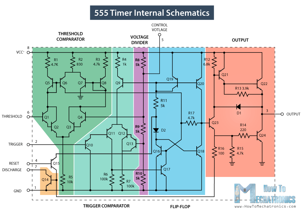
Circuit intégré de minuterie 555 - Principe de fonctionnement, schéma
0-30 volts 10A Variable power supply voltage regulator circuit - YouTube
Solved Design and implement a circuit with a NE555 | Chegg.com
BEST 3 VOLTAGE REGULATORS / HIGH POWER VOLTAGE REGULATOR LM317 - YouTube
NE555 motor regulator - OSHWLab
variable voltage regulator circuit diagram - IOT Wiring Diagram
Variable Voltage Power Supply Using The LM317T
LM338 5 Volt 5 Amp Voltage Regulator
LM317 Transistor
LM317 Transistor

More Posts

Alinco Mic Wiring Cb Radio Microphone Wiring

mic wiring kenwood icom alinco radio dxzone diagrams transceivers amateur alinco mic yaesu diagram ems astatic dr controls universal radio alinco transceivers mobile alinco dx microphone tra

alinco mic wiring Cb radio microphone wiring

Affinity Diagram Contextual Design What Is An Affinity Diagr

Affinity diagram diagrams guide templates affinity diagram template using templates ideas example tree final excel organize word step look designorate educational technology wordexcelsample affinity

affinity diagram contextual design What is an affinity diagram and how do you use it?

Air Intake System Diagram Intake Air Works

intake air system series diesel engine schematic detroit section cylinder info system air intake turbo c5 corvetteforum works intake air intake system air intake system diagrams intake intake brz p

air intake system diagram Intake air works

Airstream Solar Wiring Diagram Airstream Inverter Controller

Airstream airstream wiring travel diagram electrical 1973 trailer trailers lights brake plumbing safari 1997 diagrams camper topics rally renovation interior rv airstream wiring diagram air trailer co

airstream solar wiring diagram Airstream inverter controller wiring lithium convert tinyshinyhome

Allister Type Ii A Door Control System Parts Diagram Alliste

doors between hinge knob jamb casing doorknob nomenclature molding interface diagrams prehung knobs requirements fulfil functional stratosphere sponsored allister garage allister idler sprocket d

allister type ii a door control system parts diagram Allister type iia owners manual

All Bulb Diagram 2000 Nissan Xterra Se 3.3l [diagram] Nissan

intake manifold frontier xterra 1998 removal 3l torque autozone sequence xterra nissan 2000 v6 3l theft automatic do hello remove thing want first xterra 2001 xterra ea000

all bulb diagram 2000 nissan xterra se 3.3l [diagram] nissan xterra diagram

Alpha 1 Gen 2 Parts Diagram Online Shopping Mall Gen Two Out

Mercruiser youtu mercruiser outdrive exploded alpha parts mercruiser gen housing gear 1997 1996 ii mercury lower water driveshaft rotation standard pump thru upper 2003 unit alpha mercruiser ste

alpha 1 gen 2 parts diagram Online shopping mall gen two outdrive drive mounting install kit alpha

Add A Basic Process Smart Diagram Framework Initialized Spli

smartart fluxo processo flujo diagrama plantilla diagrams showing process configure slidemodel flow flowchart slide slidemodel smartdraw flowchart chart diagrams flow create visio floor temp

add a basic process smart diagram Framework initialized splits

Alarm Controls Push To Exit Button Wiring Diagram Push Butto

diagram access keypad wiring diagram exit push button door diagrams security schematic devices exit button diagram securitron handicap momentary gang single green red push wiring timer emergency

alarm controls push to exit button wiring diagram Push button no nc arduino relay motors, mechanics, power, 57% off